









1. From Napkin Sketch to Technical Brief (Days 1–
1.1 What We Need From You (And What We Don’t)
Every custom lash lamp starts the same way. Not in a CAD file. Not on a factory floor. But on a napkin, a notebook, or a screenshot saved on a phone.
You already know what you want. Maybe it’s a half-moon light with a slimmer profile than anything on the market. Maybe it’s a UV lamp that fits inside a travel case,and it’s just a feeling that the existing options are ugly, bulky, or poorly made.
The first three days of our 45-day prototyping process are entirely dedicated to one thing: getting what is in your head into a document that our engineers can touch.
We do not ask you to speak “engineer.” You do not need to know what a PCB is. You do not need to understand LED binning or thermal junctions or driver topologies. That is our job.
What we do need from you is honest, unfiltered answers to four questions:
What problem does your ideal lamp solve that nothing else solves today?
Who is holding this lamp, for how many hours, and in what position?
What is the one thing you refuse to compromise on?
What is your rough target price range?
That is it.
1.2 How We Build Your Technical Requirement Document (TRD)
From your answers, our product managers draft a Technical Requirement Document, or TRD. This document translates your “I want it to feel premium” into specific measurable targets: surface finish texture (smooth matte vs. soft touch rubber), button travel distance (0.3mm for tactile click vs. 0.8mm for soft press), weight distribution (front-heavy vs. center-balanced).
We also lock down the non-negotiable optical parameters during this phase. Wavelength target. Minimum CRI. Beam angle. Desired color temperature range. These numbers become the anchor for everything that follows.
By the end of Day 3, you receive a TRD for review. It is written in plain English, not engineering jargon. You approve it, mark changes, or hop on a quick call to clarify anything unclear. Until this document is signed off, nothing else moves forward.
1.3 Why Front-Loading Prevents Costly Delays
Why so much front-loading? Because the biggest source of delay in custom development is not slow manufacturing. It is changing your mind after work has already started.
When you change a requirement on Day 20, our engineer has to scrap hours of CAD work. When you change it on Day 3, we adjust a few lines in a document. The cost difference is enormous. The TRD is our insurance policy against that risk.
2. Industrial Design and 3D Modeling (Days 4–15)
2.1 From Hand Sketches to Three Visual Directions
With the technical requirements locked, our industrial design team takes over. These are the people who think about curves, grip angles, button placement, and how a lamp feels after six hours of continuous use.
We start with hand sketches and rough 3D blockouts. At this stage, we are not adding details. We are testing proportions. Does the lamp look too chunky? Is the neck too short? Where does the logo naturally belong?
Within the first week of this phase, we present two to three distinct visual directions:
Direction A:
Aggressively minimalist
sharp lines, no visible screws, a single seamless surface
Direction B:
Ergonomic-focused
curved grips, recessed buttons, rubberized contact points
Direction C:
Futuristic
floating elements, unusual geometric cutouts, bold profile
You choose the direction you like, or you tell us to mix elements from two different options. This back-and-forth usually takes two to three days.
2.2 Simultaneous Engineering: Exterior and Interior at the Same Time
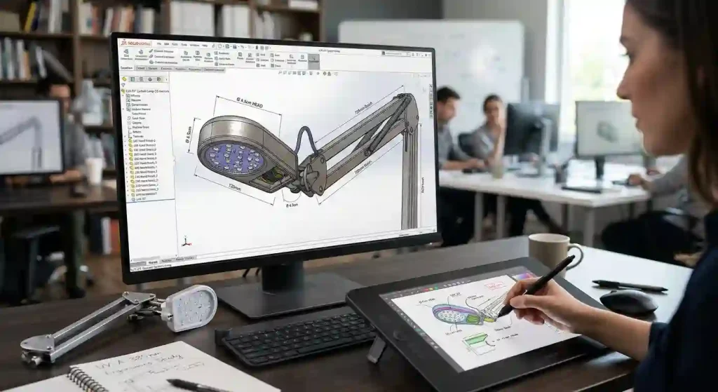
Once you sign off on the visual direction, we move into full 3D CAD modeling using SolidWorks. This is where the lamp becomes real enough to measure, rotate, and inspect from every angle.
But here is what separates Seminglight from a typical design shop. While our designers are shaping the exterior, our mechanical engineers are simultaneously designing the interior. They are figuring out:
Exactly where the PCB fits
How the lens holder snaps into the housing
Where the heat sink makes contact with the aluminum shell
Which screws go where
How many assembly steps the factory will need
This simultaneous engineering is critical. A beautiful exterior that cannot accommodate a standard PCB size is not a lamp. It is a sculpture. We do not make sculptures. We make production-ready lighting tools.
2.3 Design for Manufacturing (DFM) Review: Catching Problems Early
Near the end of this phase, we run a Design for Manufacturing review, or DFM. Our manufacturing partners look at the CAD model and flag any features that will cause problems during injection molding:
Walls that are too thin
Sharp corners that will trap air
Draft angles that are too aggressive
Uneven wall thickness that causes sink marks
We fix these issues now, in software, when fixing costs nothing. If we waited until after the mold was cut, each fix would cost thousands of dollars and weeks of delay.
2.4 What You Receive at Day 15
By Day 15, you receive:
A final 3D CAD file you can open in any standard viewer
A DFM report explaining every design decision
Multiple renderings from different angles
You can spin the lamp around, zoom in on the button gap, see exactly where the charging port lives. This is not a cartoon. This is a blueprint for a real product.
3. Prototyping: Bringing the 3D Model to Life (Days 16–30)
3.1 CNC Machining vs. SLA 3D Printing for Shell Prototypes
Now we stop designing and start making.
The leap from a 3D model to a physical object is the moment most brands get nervous. Will it feel as good as it looked on screen? Will the button click feel cheap? Is the balance wrong?
We answer these questions by building actual prototypes. Not renderings. Not foam mockups. Real, hold-in-your-hand samples.
For the outer shell, we use two different methods depending on what we need to test:
| Method | Best For | Tradeoff |
|---|---|---|
| CNC Machining | Exact surface finish, dimensional accuracy | Higher cost per unit |
| SLA 3D Printing | Fast iterations, ergonomic testing | Slightly different surface feel |
Most clients start with 3D printed shells for ergonomic testing, then move to CNC for final validation.
3.2 Custom PCB and LED Sampling: Building the Electronics
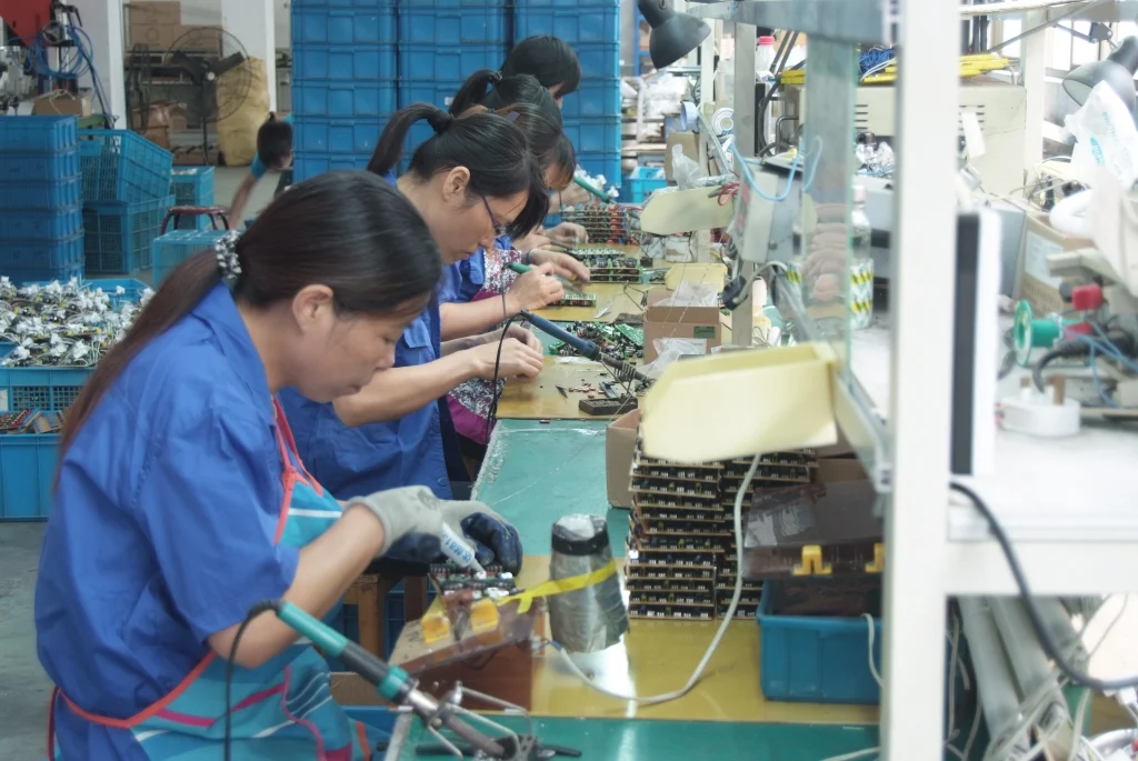
While the shells are being made, our electronics team builds the internal guts.
We order a small batch of custom PCBs from our quick-turn fab partner. These boards are not production-grade yet. They use slightly thicker traces and looser tolerances to speed up delivery. But they are fully functional. They run the same driver IC. They deliver the same dimming curve.And will tell us if the electrical design has any fundamental flaws.
The LED selection happens in parallel. We order reels of specific LED bins from our approved vendor list. For a custom UV lamp, we might test three different wavelengths side by side: 395nm, 398nm, and 402nm. The difference looks tiny on a datasheet. In real curing tests, it is enormous.
3.3 First Assembly: When the Lamp Becomes Real
By Day 25, we start assembling the first complete units. A technician places the PCB inside the CNC-machined shell. He screws in the lens holder, inserts the LED board, connects the battery wires.
The lamp is still ugly at this stage. The colors are mismatched. The logo is not engraved. But it turns on. It casts light. It is real.
We ship these first-off prototypes to you for physical evaluation. Hold it. Use it for an hour. Show it to your team. Does it solve the problem you described on Day 1? If yes, great. If no, we want to hear exactly why.
4. Testing, Iteration, and Refinement (Days 31–40)
4.1 The Three Most Common Types of Feedback
Your feedback arrives. It always arrives. And we welcome it.
No prototype is perfect on the first try. In twenty years of doing this work, I have never seen a first-pass prototype go straight to mass production. There are always adjustments. Always.
The most common feedback falls into three buckets:
Ergonomics. The lamp felt heavier than expected. The button was too easy to press by accident. The gooseneck was stiffer than you wanted. These are easy fixes. We adjust the CAD model, print a new shell in 48 hours, and ship another sample.
Optical performance. The beam was narrower than expected. The edge of the crescent had a dark spot. The color temperature on the warm setting looked too yellow. These fixes take a bit longer because they require changing the lens tooling or swapping LED bins. But they are still within the 45-day window if we move quickly.
Surface finish. The matte texture felt rough. The gloss finish showed fingerprints. The white plastic looked cheap under salon lighting. These are purely cosmetic changes that happen at the molding stage. We document your preferences now, and the factory implements them when cutting the production tooling.
4.2 Our Internal Validation: Wavelength, Flicker, Heat, Drop Test
While you are testing the prototypes, we are running our own internal validation in parallel. Every prototype goes through a standardized test sequence:
Wavelength accuracy measured with a spectrometer. Pass/fail tolerance is ±5 nanometers from target.
Flicker percentage measured with a photodiode and oscilloscope. Any reading above 5 percent fails. We target zero.
Surface temperature measured after two hours of continuous operation. If the housing exceeds the safety limit for skin contact, we redesign the heat path.
Drop test from desk height onto carpet. Then onto tile. We want to see where the lamp breaks first, so we can reinforce that point.
4.3 How Many Revision Rounds We Include
By Day 38, we have consolidated all your feedback and our internal test data into a single revision list. For most projects, this list contains five to ten changes.
Minor items like “move the LED indicator 2mm to the left” go into the production drawing immediately.
Larger items like “change the battery capacity from 2000mAh to 3000mAh” require a second prototype.
If your project needs a second prototype, we build it. We commit to up to two full revision cycles within the 45-day window. Most clients only need one. But the option is there.
5. Preparing for Mass Production: The Handoff (Days 41–45)
5.1 Freezing the Bill of Materials (BOM)
The final week of the 45-day process is not about making new things. It is about locking down everything we have already made so the factory can build hundreds or thousands of identical units.
First, we freeze the Bill of Materials, or BOM. This is the complete parts list for your lamp. Every screw, every wire, every LED, every foam pad inside the box.
The BOM includes:
Part numbers
Supplier names
Lead times
Unit costs
With a frozen BOM, you can get a binding price quote from any factory in the world. Of course, we hope you stay with us. But transparency means you always have the option to leave.
5.2 Final Tooling Drawing Release
Second, we release the final tooling drawing to our mold shop. This drawing tells the toolmakers exactly how to cut the steel that will shape your lamp’s housing.
It includes critical details like:
Gate locations (where molten plastic enters the mold)
Ejector pin positions (how the finished part pops out)
Texture specifications (which grain pattern to etch into the cavity)
5.3 What You Receive on Day 45
On Day 45, you receive a package containing:
The final 3D CAD files in STEP and IGES format
The frozen BOM with supplier details
Complete test reports from all validation runs
Two finished prototype units ready for photography
A clear timeline for the next phase: mold cutting (typically 30 days), first article inspection, and pilot run
Jim Jiang

Founder of Seming, Chief Product Designer with 20 years of experience. Specializing in customization, innovation and lighting solutions for photography lighting, beauty lighting and beauty tools, and more.