








1. Del boceto en una servilleta al pliego de condiciones técnicas (Días 1–
1.1 Lo que necesitamos de ti (y lo que no)
Todas las lámparas para pestañas personalizadas nacen de la misma manera. No en un archivo CAD. Ni en la planta de producción. Sino en una servilleta, un cuaderno o una captura de pantalla guardada en un móvil.
Ya sabes lo que quieres. Quizá sea una lámpara con forma de media luna con un perfil más estilizado que cualquier otra del mercado. Quizá sea una lámpara UV que quepa en un estuche de viaje, y simplemente tienes la sensación de que las opciones actuales son feas, voluminosas o de mala calidad.
Los tres primeros días de nuestro proceso de creación de prototipos, de 45 días de duración, se dedican por completo a una sola cosa: plasmar lo que tienes en mente en un documento con el que nuestros ingenieros puedan trabajar.
No te pedimos que hables “como un ingeniero”. No hace falta que sepas qué es una PCB. Tampoco hace falta que entiendas en qué consiste la clasificación de los LED, las uniones térmicas o las topologías de los controladores. Eso es cosa nuestra.
Lo que sí necesitamos de ti son respuestas sinceras y sin tapujos a cuatro preguntas:
¿Qué problema resuelve tu lámpara ideal que hoy en día no resuelve ningún otro producto?
¿Quién sostiene esta lámpara, durante cuántas horas y en qué posición?
¿Cuál es la única cosa en la que no estás dispuesto a ceder?
¿Cuál es, más o menos, tu rango de precios objetivo?
Eso es todo.
1.2 Cómo elaboramos tu documento de requisitos técnicos (TRD)
A partir de vuestras respuestas, nuestros responsables de producto elaboran un Documento de Requisitos Técnicos (TRD). Este documento traduce tu “quiero que transmita una sensación de alta gama” en objetivos específicos y cuantificables: textura del acabado superficial (mate liso frente a goma de tacto suave), recorrido de los botones (0,3 mm para un clic táctil frente a 0,8 mm para una pulsación suave) y distribución del peso (más peso en la parte delantera frente a equilibrio central).
En esta fase también fijamos los parámetros ópticos no negociables. Longitud de onda objetivo. Mínimo índice de reproducción cromática. Ángulo de haz. Rango de temperatura de color deseado. Estas cifras sirven de referencia para todo lo que viene a continuación.
Al final del tercer día, recibirás un TRD para que lo revises. Está redactado en un inglés sencillo, sin jerga técnica. Lo apruebas, señalas los cambios o haces una llamada rápida para aclarar cualquier duda. Hasta que no se apruebe este documento, no se avanza en nada más.
1.3 Por qué la planificación anticipada evita retrasos costosos
¿Por qué se concentra tanto el trabajo al principio? Porque la principal causa de retraso en el desarrollo a medida no es la lentitud de la fabricación, sino el hecho de cambiar de opinión una vez que el trabajo ya ha comenzado.
Cuando se modifica un requisito el día 20, nuestro ingeniero tiene que descartar horas de trabajo en CAD. Cuando se modifica el día 3, solo tenemos que ajustar unas pocas líneas en un documento. La diferencia de coste es enorme. El TRD es nuestra póliza de seguro frente a ese riesgo.
2. Diseño industrial y modelado 3D (días 4 a 15)
2.1 De los bocetos a mano a tres líneas visuales
Una vez definidos los requisitos técnicos, nuestro equipo de diseño industrial toma el relevo. Son ellos quienes se ocupan de las curvas, los ángulos de agarre, la ubicación de los botones y la sensación que transmite una lámpara tras seis horas de uso continuo.
Empezamos con bocetos a mano y esbozos preliminares en 3D. En esta fase, no añadimos detalles. Lo que hacemos es comprobar las proporciones. ¿La lámpara parece demasiado voluminosa? ¿El cuello es demasiado corto? ¿Dónde encaja de forma natural el logotipo?
Durante la primera semana de esta fase, presentamos entre dos y tres líneas visuales distintas:
Dirección A:
Minimalista a más no poder
líneas nítidas, sin tornillos a la vista, una única superficie sin juntas
Dirección B:
Centrado en la ergonomía
curved grips, recessed buttons, rubberized contact points
Direction C:
Futuristic
floating elements, unusual geometric cutouts, bold profile
You choose the direction you like, or you tell us to mix elements from two different options. This back-and-forth usually takes two to three days.
2.2 Ingeniería simultánea: exterior e interior al mismo tiempo
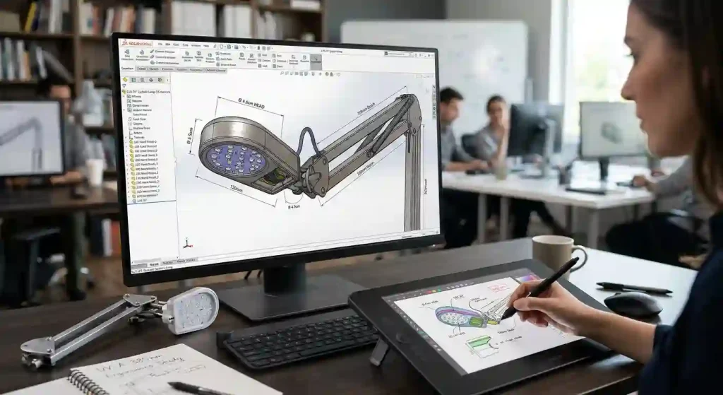
Once you sign off on the visual direction, we move into full 3D CAD modeling using SolidWorks. This is where the lamp becomes real enough to measure, rotate, and inspect from every angle.
But here is what separates Seminglight from a typical design shop. While our designers are shaping the exterior, our mechanical engineers are simultaneously designing the interior. They are figuring out:
Exactly where the PCB fits
How the lens holder snaps into the housing
Where the heat sink makes contact with the aluminum shell
Which screws go where
How many assembly steps the factory will need
This simultaneous engineering is critical. A beautiful exterior that cannot accommodate a standard PCB size is not a lamp. It is a sculpture. We do not make sculptures. We make production-ready lighting tools.
2.3 Revisión del diseño para la fabricación (DFM): detección temprana de problemas
Near the end of this phase, we run a Design for Manufacturing review, or DFM. Our manufacturing partners look at the CAD model and flag any features that will cause problems during injection molding:
Walls that are too thin
Sharp corners that will trap air
Draft angles that are too aggressive
Uneven wall thickness that causes sink marks
We fix these issues now, in software, when fixing costs nothing. If we waited until after the mold was cut, each fix would cost thousands of dollars and weeks of delay.
2.4 Lo que recibirás el día 15
By Day 15, you receive:
A final 3D CAD file you can open in any standard viewer
A DFM report explaining every design decision
Multiple renderings from different angles
You can spin the lamp around, zoom in on the button gap, see exactly where the charging port lives. This is not a cartoon. This is a blueprint for a real product.
3. Creación de prototipos: dar vida al modelo 3D (días 16-30)
3.1 Mecanizado CNC frente a impresión 3D SLA para prototipos de carcasas
Now we stop designing and start making.
The leap from a 3D model to a physical object is the moment most brands get nervous. Will it feel as good as it looked on screen? Will the button click feel cheap? Is the balance wrong?
We answer these questions by building actual prototypes. Not renderings. Not foam mockups. Real, hold-in-your-hand samples.
For the outer shell, we use two different methods depending on what we need to test:
| Método | Lo mejor para | Tradeoff |
|---|---|---|
| CNC Machining | Exact surface finish, dimensional accuracy | Higher cost per unit |
| SLA 3D Printing | Fast iterations, ergonomic testing | Slightly different surface feel |
Most clients start with 3D printed shells for ergonomic testing, then move to CNC for final validation.
3.2 Muestras de placas de circuito impreso personalizadas y LED: montaje de los componentes electrónicos
While the shells are being made, our electronics team builds the internal guts.
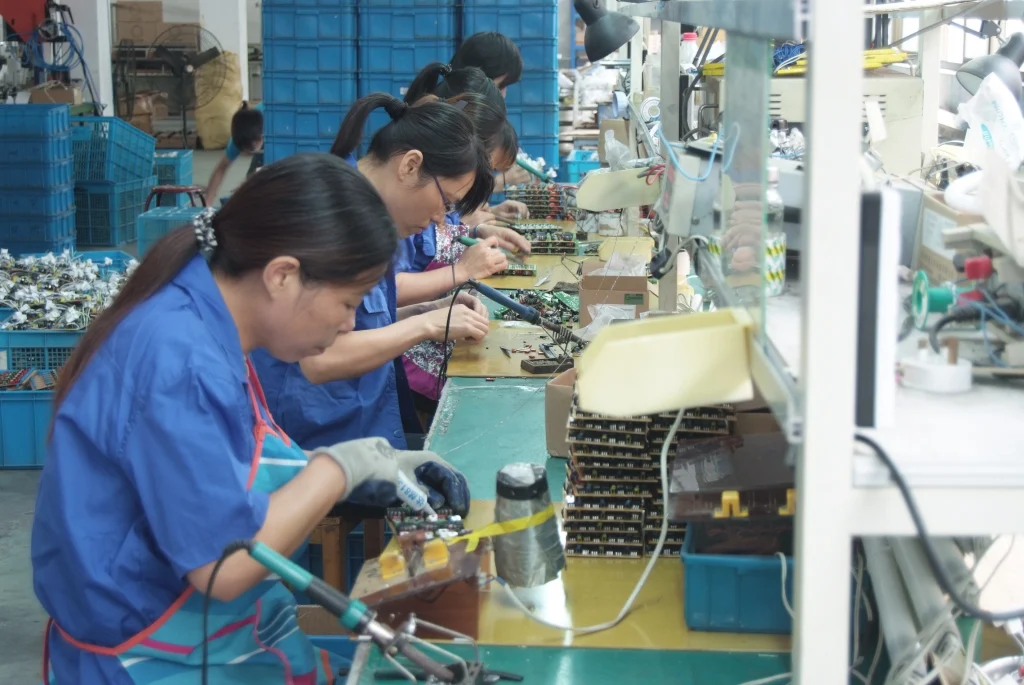
We order a small batch of custom PCBs from our quick-turn fab partner. These boards are not production-grade yet. They use slightly thicker traces and looser tolerances to speed up delivery. But they are fully functional. They run the same driver IC. They deliver the same dimming curve.And will tell us if the electrical design has any fundamental flaws.
The LED selection happens in parallel. We order reels of specific LED bins from our approved vendor list. For a custom UV lamp, we might test three different wavelengths side by side: 395nm, 398nm, and 402nm. The difference looks tiny on a datasheet. In real curing tests, it is enormous.
3.3 Primer montaje: cuando la lámpara cobra vida
By Day 25, we start assembling the first complete units. A technician places the PCB inside the CNC-machined shell. He screws in the lens holder, inserts the LED board, connects the battery wires.
The lamp is still ugly at this stage. The colors are mismatched. The logo is not engraved. But it turns on. It casts light. It is real.
We ship these first-off prototypes to you for physical evaluation. Hold it. Use it for an hour. Show it to your team. Does it solve the problem you described on Day 1? If yes, great. If no, we want to hear exactly why.
4. Pruebas, iteración y perfeccionamiento (días 31-40)
4.1 Los tres tipos más comunes de comentarios
Your feedback arrives. It always arrives. And we welcome it.
No prototype is perfect on the first try. In twenty years of doing this work, I have never seen a first-pass prototype go straight to mass production. There are always adjustments. Always.
The most common feedback falls into three buckets:
Ergonomics. The lamp felt heavier than expected. The button was too easy to press by accident. The gooseneck was stiffer than you wanted. These are easy fixes. We adjust the CAD model, print a new shell in 48 hours, and ship another sample.
Optical performance. The beam was narrower than expected. The edge of the crescent had a dark spot. The color temperature on the warm setting looked too yellow. These fixes take a bit longer because they require changing the lens tooling or swapping LED bins. But they are still within the 45-day window if we move quickly.
Surface finish. The matte texture felt rough. The gloss finish showed fingerprints. The white plastic looked cheap under salon lighting. These are purely cosmetic changes that happen at the molding stage. We document your preferences now, and the factory implements them when cutting the production tooling.
4.2 Nuestra validación interna: longitud de onda, parpadeo, calor, ensayo de caída
While you are testing the prototypes, we are running our own internal validation in parallel. Every prototype goes through a standardized test sequence:
Wavelength accuracy measured with a spectrometer. Pass/fail tolerance is ±5 nanometers from target.
Flicker percentage measured with a photodiode and oscilloscope. Any reading above 5 percent fails. We target zero.
Surface temperature measured after two hours of continuous operation. If the housing exceeds the safety limit for skin contact, we redesign the heat path.
Drop test from desk height onto carpet. Then onto tile. We want to see where the lamp breaks first, so we can reinforce that point.
4.3 Cuántas rondas de revisión incluimos
By Day 38, we have consolidated all your feedback and our internal test data into a single revision list. For most projects, this list contains five to ten changes.
Minor items like “move the LED indicator 2mm to the left” go into the production drawing immediately.
Larger items like “change the battery capacity from 2000mAh to 3000mAh” require a second prototype.
If your project needs a second prototype, we build it. We commit to up to two full revision cycles within the 45-day window. Most clients only need one. But the option is there.
5. Preparación para la producción en serie: el traspaso (días 41-45)
5.1 Congelación de la lista de materiales (BOM)
The final week of the 45-day process is not about making new things. It is about locking down everything we have already made so the factory can build hundreds or thousands of identical units.
First, we freeze the Bill of Materials, or BOM. This is the complete parts list for your lamp. Every screw, every wire, every LED, every foam pad inside the box.
The BOM includes:
Part numbers
Supplier names
Lead times
Unit costs
With a frozen BOM, you can get a binding price quote from any factory in the world. Of course, we hope you stay with us. But transparency means you always have the option to leave.
5.2 Aprobación del plano definitivo de los utillajes
Second, we release the final tooling drawing to our mold shop. This drawing tells the toolmakers exactly how to cut the steel that will shape your lamp’s housing.
It includes critical details like:
Gate locations (where molten plastic enters the mold)
Ejector pin positions (how the finished part pops out)
Texture specifications (which grain pattern to etch into the cavity)
5.3 Lo que recibirás el día 45
On Day 45, you receive a package containing:
En final 3D CAD files in STEP and IGES format
The frozen BOM with supplier details
Complete test reports from all validation runs
Two finished prototype units ready for photography
A clear timeline for the next phase: mold cutting (typically 30 days), first article inspection, and pilot run
Jim Jiang

Fundador de Seming, diseñador jefe de productos con 20 años de experiencia. Especializado en personalización, innovación y soluciones de iluminación para iluminación fotográfica, iluminación de belleza y herramientas de belleza, y mucho más.